Build the ROSMO Robot
Welcome to the ROSMO robot assembly guide! This guide will walk you through the steps to build your ROSMO robot. By the end, you’ll have a fully operational robot, ready for exploration and experimentation. Whether you’re a beginner or experienced in robotics, this guide will provide all the details you need.
Parts List
Before you begin, ensure you have all the necessary parts:
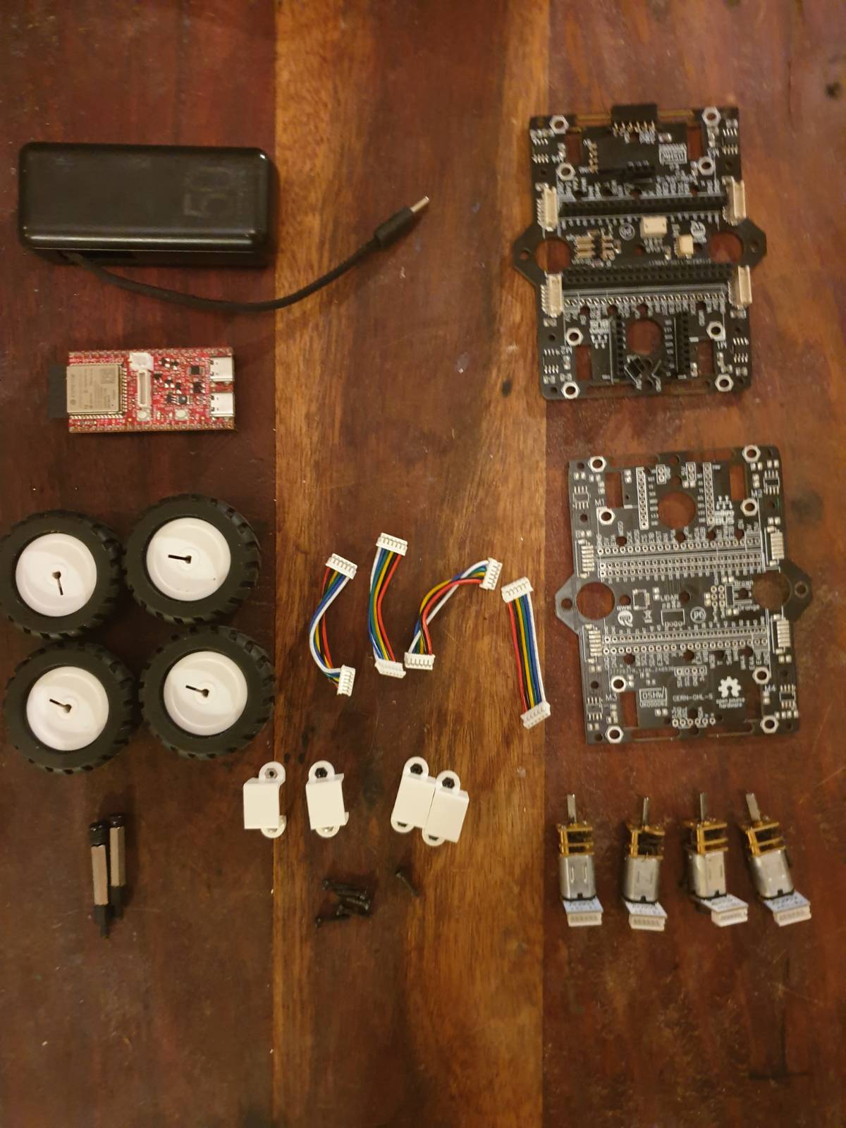
Refer to the homepage for comprehensive list & links to parts
Tools Needed
You’ll need the following tools:
3mm Hex key (usually provided in M3 nut/bolt kits)
Assembly Steps
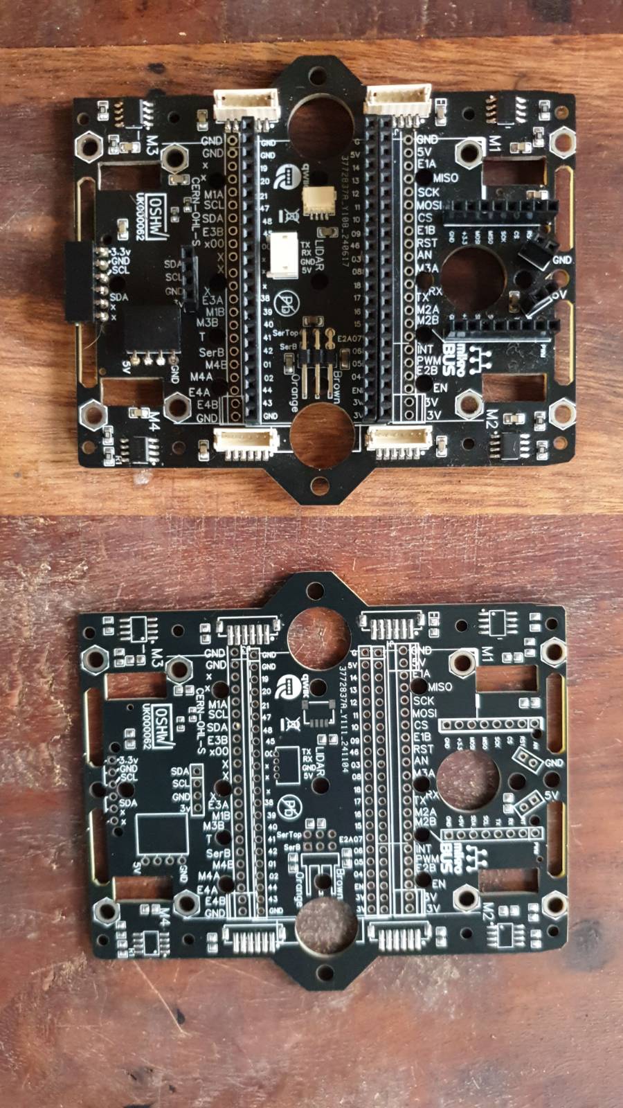
The chassis is a two printed circuit boards with the battery sandwiched between. All the essential robot parts simplypress onto the headers to make assembly as simple as possible. You can also 3D print your own parts to attach to the chassis. The first plate you need is the unfabricated one, with no parts attached to it. Use this as the bottom plate.
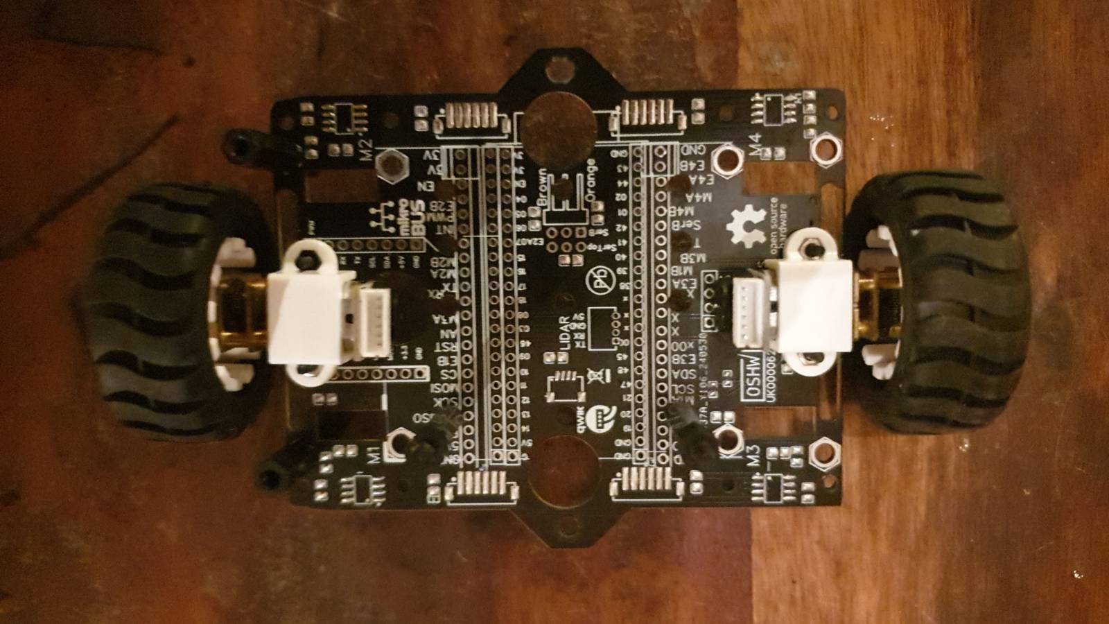
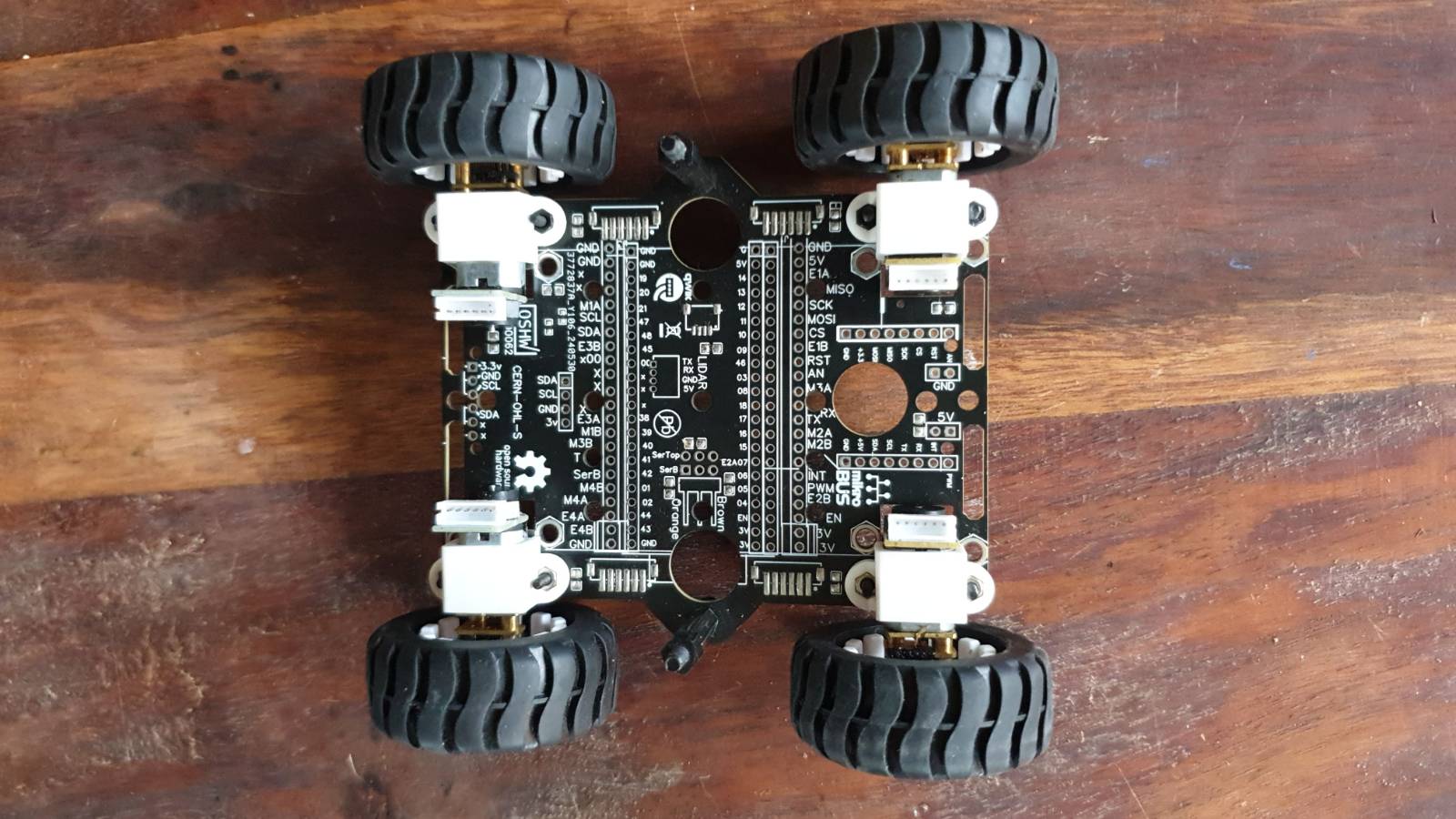
Mounting Motors and Wheels
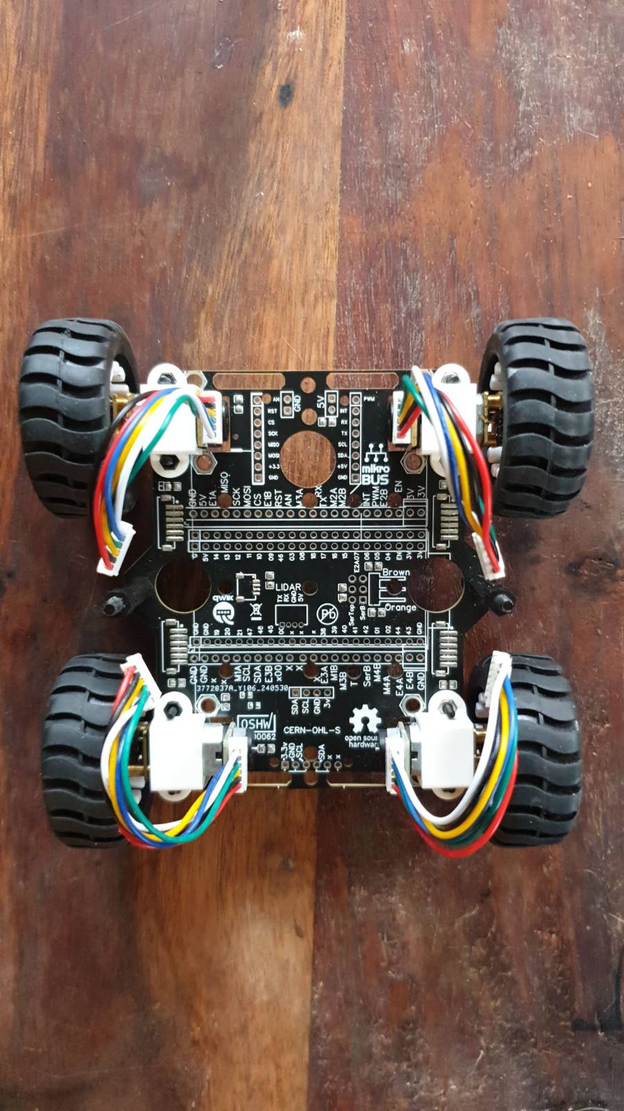
Attach Wheels: Press-fit each wheel onto the motor shafts, pushing down and forward for a snug fit. Install Motors: Place each motor into its designated place on the frame, ensuring the encoder connections face inward and upwards. Secure Motors: Use included plastic clip and screws to fasten each motor firmly.
2WD configuration
4WD configuration
Attach motor cables
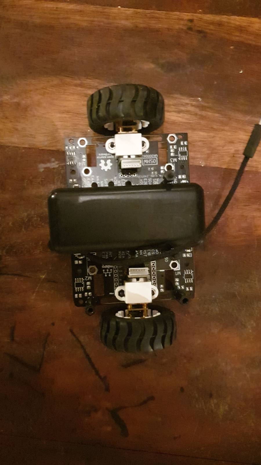
Place the battery between the motors
2WD configuration
4WD configuration
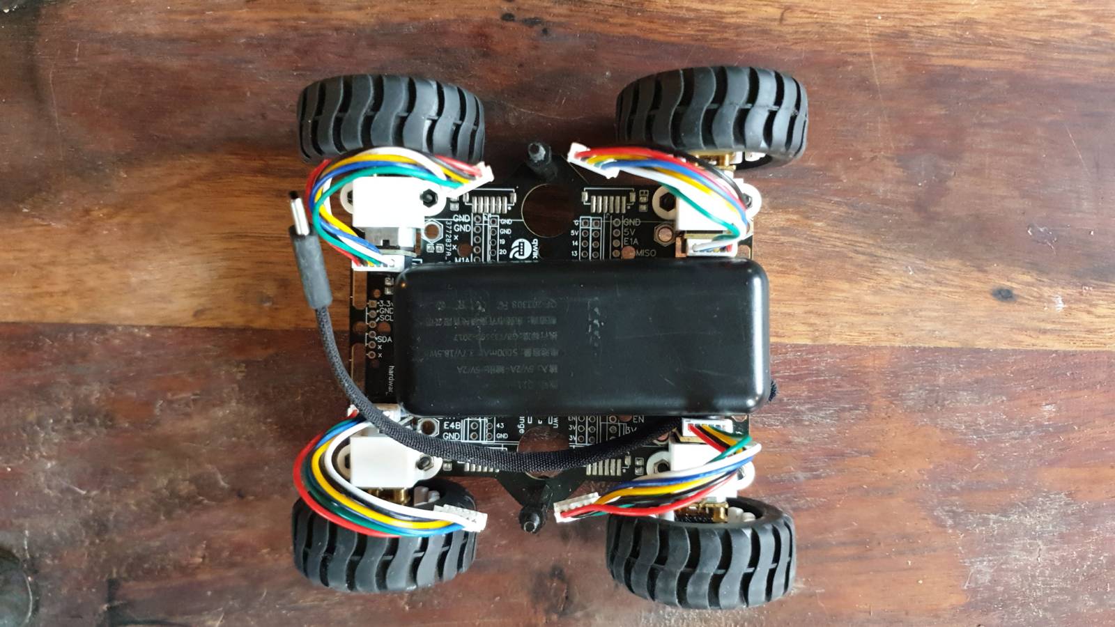
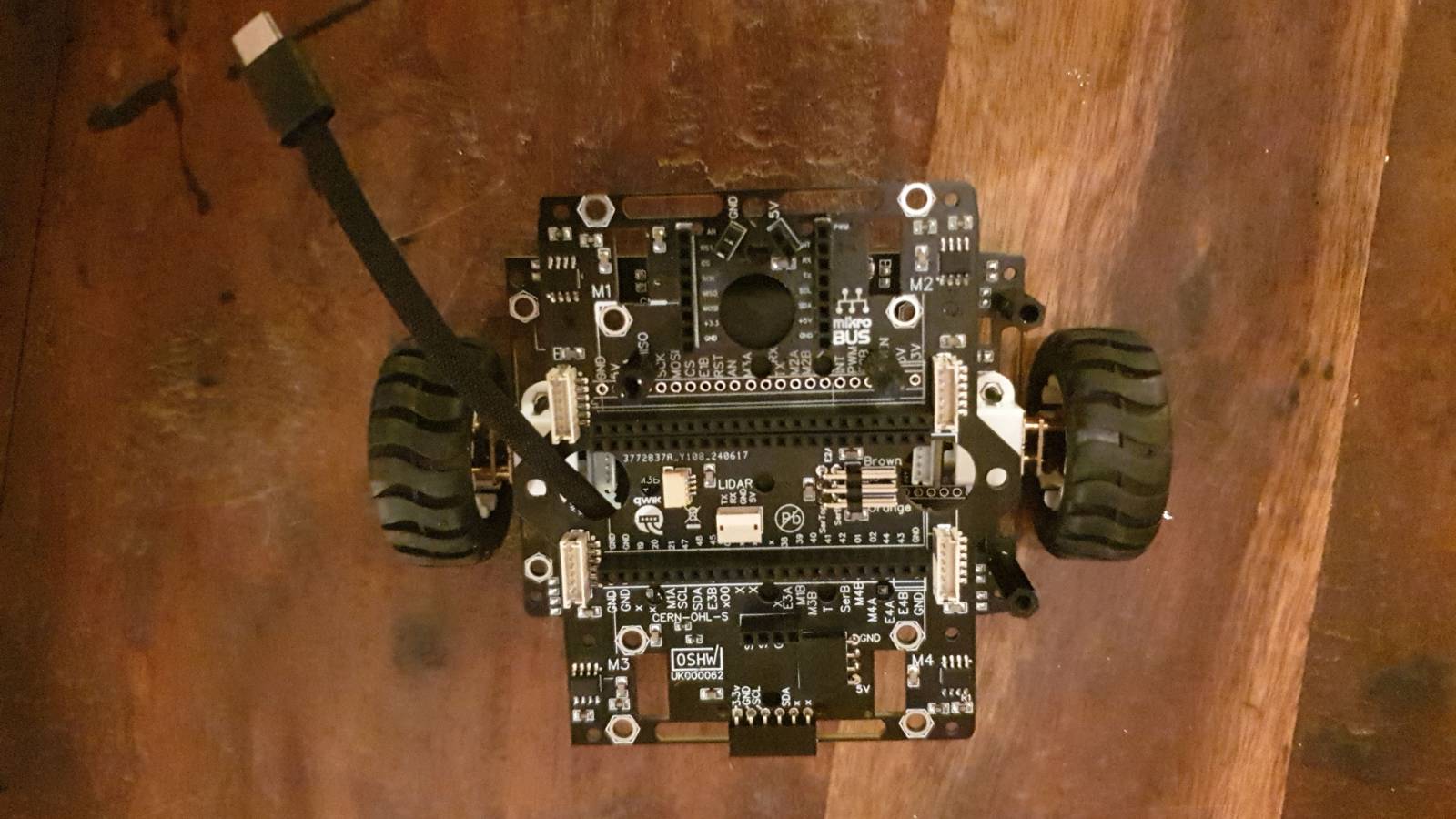
Add second plate
Now grab the plate with components on it/
Pass the motor cables through the holes. Align the chassis pieces and secure them with the standoffs provided.
2WD configuration
Wiring and Connections
Motor Connections: Connect the motors to the designated ports on the chassis.
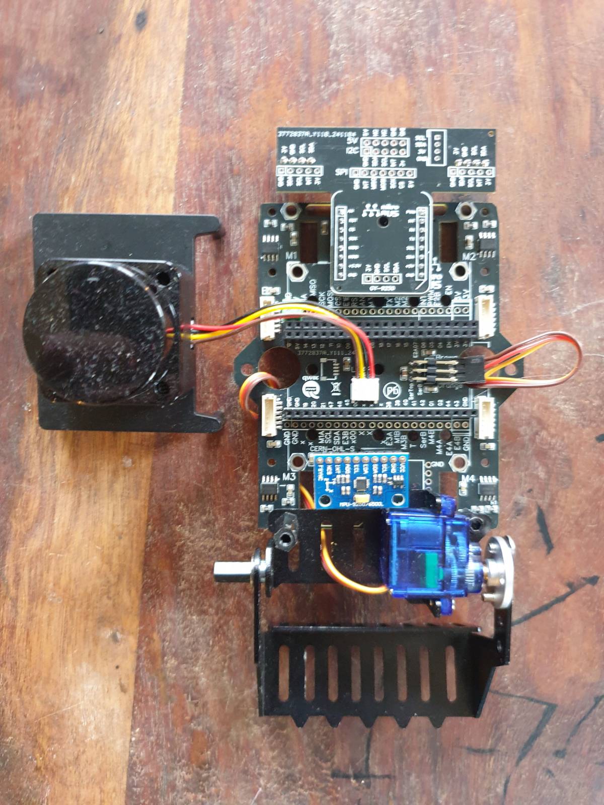
Connect Lidar and Servo(s)
If you have a lidar or servos to connect do it now
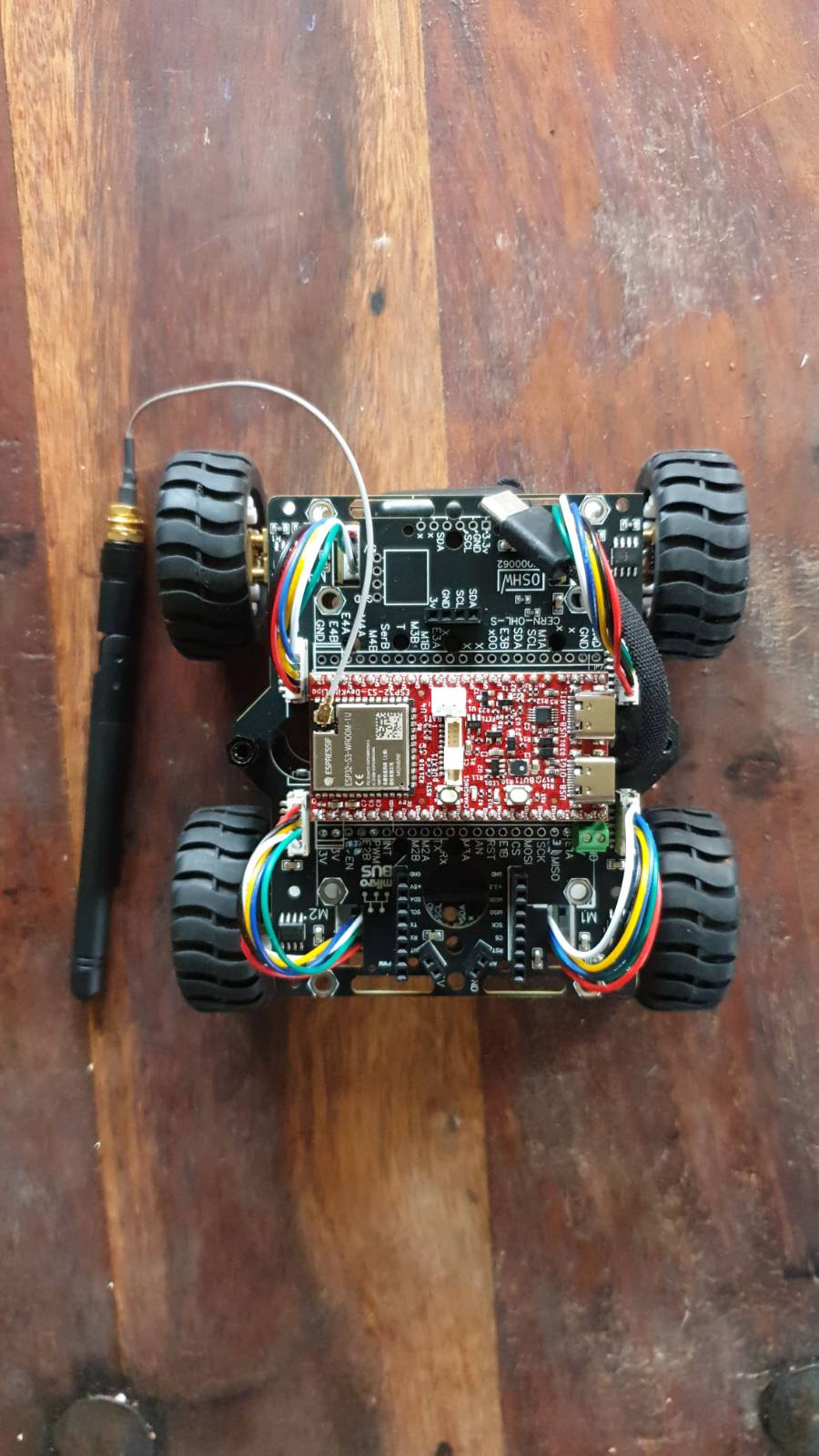
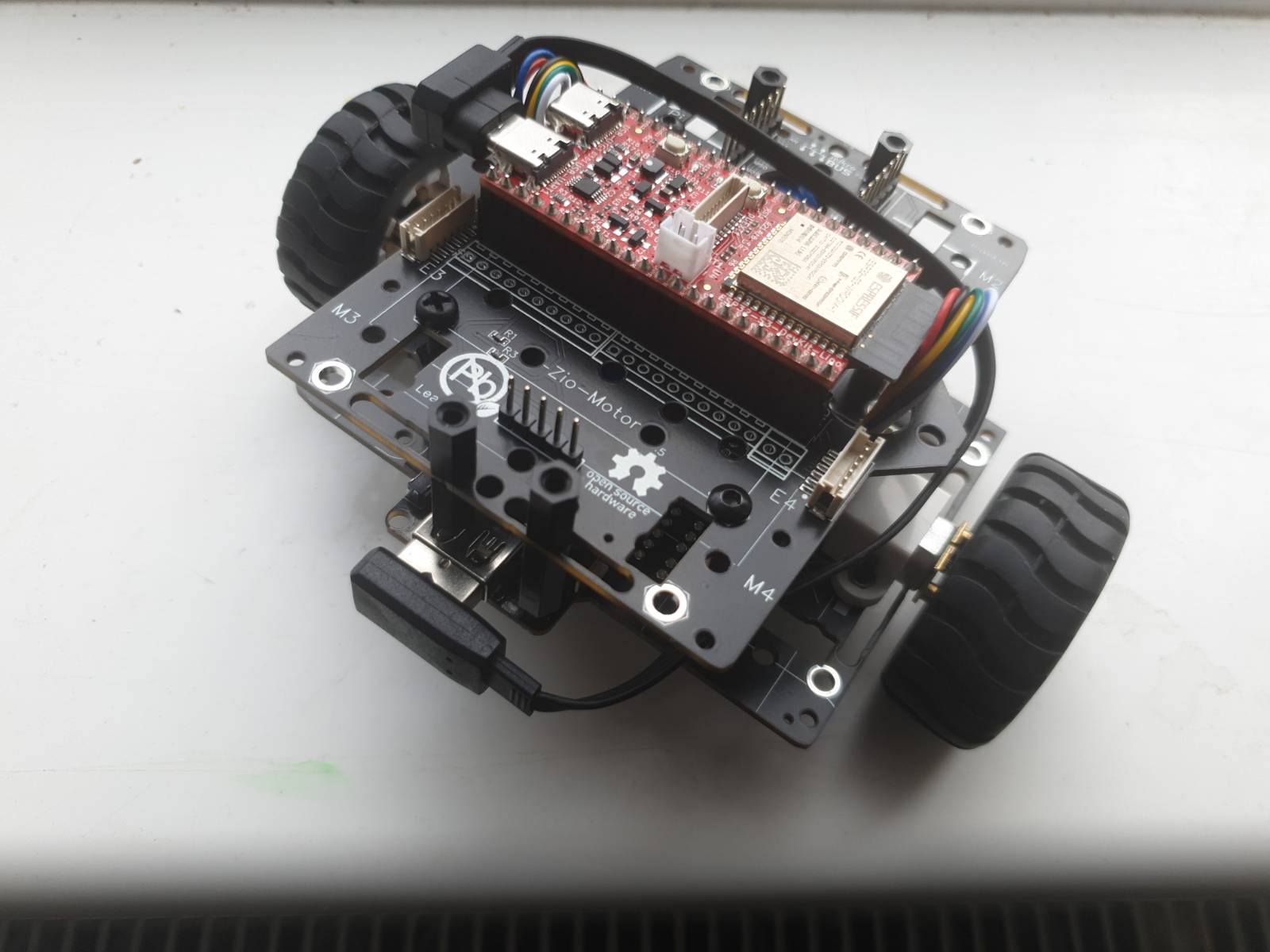
Plug in the ESP32-S3 Processor
Position the ESP32-S3 processor on the headers. Ensure its mounted in the correct orientation!
2WD
For For 4WD configuration it looks like this:
Adding Sensors
IMU Sensor: Place the IMU sensor on the top frame section. connect using a Qwiic cable or pin header
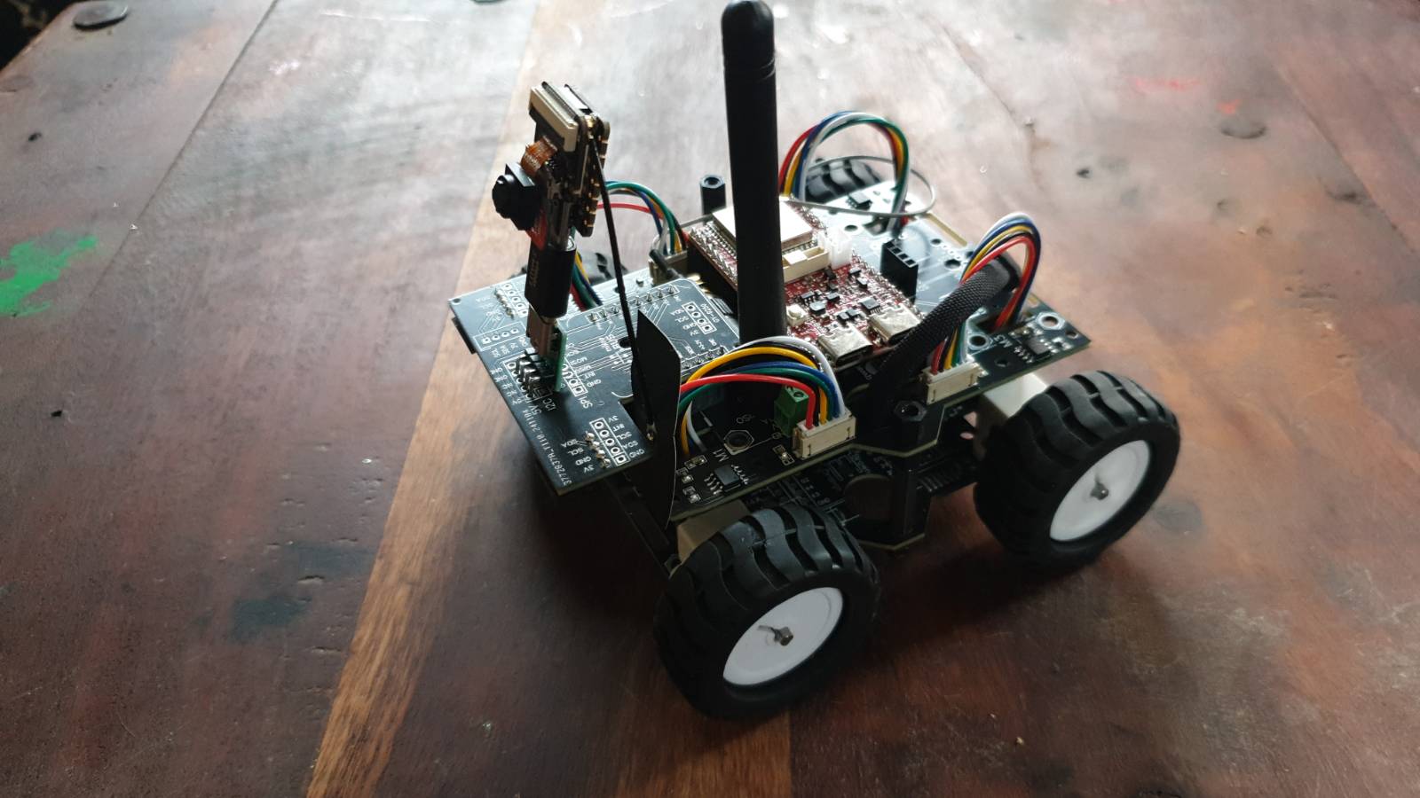
For 2WD or 4WD configuration it looks like this:

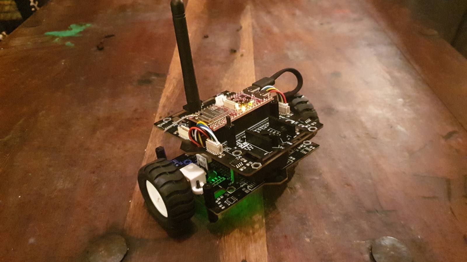
Complete robot
Testing and Calibration
Initial Test: Power on your robot and check each component (motors, sensors, etc.) for responsiveness. Motor Alignment: Test the motors to ensure they rotate in the correct direction. Adjust if necessary.
Adding extra components

Please refer to the homepage for links to tested components
Getting help
We have set up a Discord channel where you can get help from our team as well as members of the community using Rosmo & the Linorobot ROS2 software.